How to choose piezo ceramic disc?
Piezo Ceramic Disc Selection Guide:
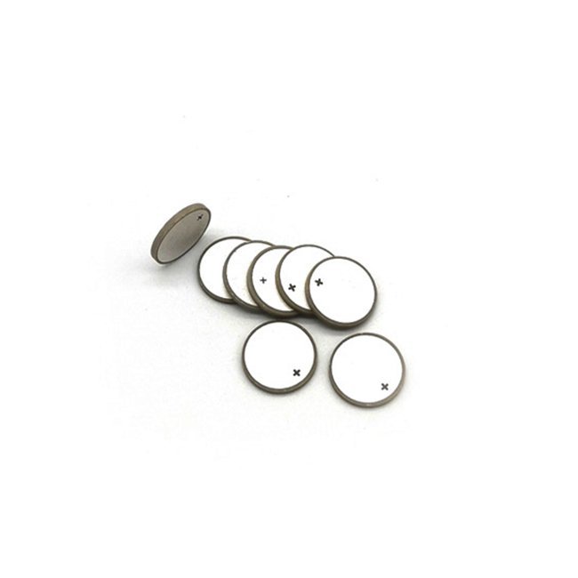
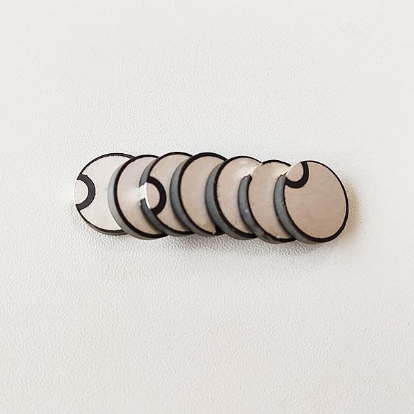
1. choose type A (electrode on both sides), diameter 8mm 1mhz, write to us part number “N4P8A1000″, type B”N4P8B1000”.
2. N4P Represents PZT4 material.
3. We also provide PZT5 and PZT8 material, N5P represents PZT5, N8P represents PZT8.


Piezo ceramic disc parameter sheet:
| Part No. | Specification ( mm ) | Capacitance ( pF ) | Resonant Frequency ( Mhz ) | Impedance ( Ω ) | Coupling Coefficient ( Kp%/Kt% ) | Diameter (mm) | Thickness (mm) |
| N4P81000 | Φ8×2 | 500±15% | 1 | 2 | ≥55 | 8 | 2 |
| N4P82000 | Φ8×1 | 650±15% | 2 | 2 | ≥55 | 8 | 1 |
| N4P83000 | Φ8×0.75 | 800±15% | 3 | 2 | ≥55 | 8 | 0.75 |
| N4P85000 | Φ8×0.45 | 1000±15% | 5 | 2 | ≥55 | 8 | 0.45 |
| N4P101000 | Φ10×2 | 600±15% | 1 | 2 | ≥55 | 10 | 2 |
| N4P102000 | Φ10×1 | 800±15% | 2 | 2 | ≥55 | 10 | 1 |
| N4P103000 | Φ10×0.75 | 1000±15% | 3 | 2 | ≥55 | 10 | 0.75 |
| N4P105000 | Φ10×0.45 | 1200±15% | 5 | 2 | ≥55 | 10 | 0.45 |
| N4P121000 | Φ12×2 | 1300±15% | 1 | 2 | ≥55 | 12 | 2 |
| N4P122000 | Φ12×1 | 1500±15% | 2 | 2 | ≥55 | 12 | 1 |
| N4P123000 | Φ12×0.75 | 1600±15% | 3 | 2 | ≥55 | 12 | 0.75 |
| N4P125000 | Φ12×0.45 | 1900±15% | 5 | 2 | ≥55 | 12 | 0.45 |
| N4P151000 | Φ15×2 | 1600±15% | 1 | 2 | ≥55 | 15 | 2 |
| N4P152000 | Φ15×1 | 2000±15% | 2 | 2 | ≥55 | 15 | 1 |
| N4P153000 | Φ15×0.75 | 3800±15% | 3 | 2 | ≥55 | 15 | 0.75 |
| N4P155000 | Φ15×0.45 | 6500±15% | 5 | 2 | ≥55 | 15 | 0.45 |
| N4P161000 | Φ16×2 | 1000±15% | 1 | 2 | ≥55 | 16 | 2 |
| N4P162000 | Φ16×1 | 2000±15% | 2 | 2 | ≥55 | 16 | 1 |
| N4P163000 | Φ16×0.75 | 4300±15% | 3 | 2 | ≥55 | 16 | 0.75 |
| N4P165000 | Φ16×0.45 | 6800±15% | 5 | 2 | ≥55 | 16 | 0.45 |
| N4P201000 | Φ20×2 | 2000±15% | 1 | 2 | ≥55 | 20 | 2 |
| N4P202000 | Φ20×1 | 3800±15% | 2 | 2 | ≥55 | 20 | 1 |
| N4P203000 | Φ20×0.73 | 4600±15% | 3 | 2 | ≥55 | 20 | 0.73 |
| N4P205000 | Φ20×0.42 | 7000±15% | 5 | 2 | ≥55 | 20 | 0.42 |
| N4P251000 | Φ25×2 | 2100±15% | 1 | 2 | ≥55 | 25 | 2 |
| N4P253000 | Φ25×0.73 | 5600±15% | 3 | 2 | ≥55 | 25 | 0.73 |
| N4P255000 | Φ25×0.43 | 8500±15% | 5 | 2 | ≥55 | 25 | 0.43 |
| N4P281000 | Φ28×2 | 3600±15% | 1 | 2 | ≥55 | 28 | 2 |
| N4P282000 | Φ28×1 | 6800±15% | 2 | 2 | ≥55 | 28 | 1 |
| N4P283000 | Φ28×0.73 | 9600±15% | 3 | 2 | ≥55 | 28 | 0.73 |
| N4P301000 | Φ30*2 | 3600±15% | 1 | 2 | ≥55 | 30 | 2 |
| N4P302000 | Φ30*1 | 6900±15% | 2 | 2 | ≥55 | 30 | 1 |
| N4P401000 | Φ40*2 | 8500±15% | 1 | 2 | ≥55 | 40 | 2 |
| N4P401500 | Φ40*1.5 | 9000±15% | 1.5 | 2 | ≥55 | 40 | 1.5 |
| N4P500830 | Φ50*2.5 | 9000±15% | 8.3 | 2 | ≥55 | 50 | 2.5 |
| N4P501000 | Φ50*2 | 9300±15% | 1 | 2 | ≥55 | 50 | 2 |
| N4P502000 | Φ50*1 | 9600±15% | 2 | 2 | ≥55 | 50 | 1 |
Piezo Ceramic Disc Material Application:
The common “hard” piezoceramic materials utilized in power ultrasonic transducers are PZT8 and PZT4 (e.g., welding, cutting, sonar, etc.).
Because of its greater mechanical quality factor Qm, PZT8 is thought to be the preferable choice for resonant devices.
In comparison to PZT4, PZT8 is regarded as a “harder” material since it has superior stability at higher preloads and driving levels.
Despite obvious benefits like increased output, many transducer designers never consider PZT4 for their applications (i.e., higher d33).
If mechanical joint losses prevail, even the perceived advantage of PZT8 in terms of Qm may not be significant for most Langevin, bolted stack type transducers. The performance of identical ultrasonic transducers used for semiconductor wire bonding, built with either PZT8 or PZT4 materials, is the subject of this study.
